Figure 3.2.1 VTA Data Specification Window
Chapter 3. Using VTA
The VTA user wizard will guide the user to select data source, set up filter expression while capturing, select views and choose operation mode. It consists of four or five steps depending on the operation mode the user chooses. When VTA starts, it will pop up automatically. The user can also launch it from the File menu.
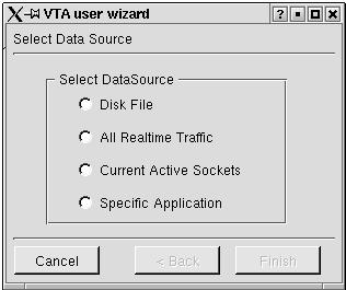
3.2.1 Data Specification Window
The first window of the user wizard is the Data Specification Window. A user may select one from among the options Disk File, All Realtime Traffic, Current Active Sockets, or Specific Application as the initial source of the packet stream which feeds into the VTA views.
Figure 3.2.1 VTA Data Specification Window
If the user chooses disk file in the VTA data specification window, he will be presented with a file selection dialog. Following that, he will be brought to the capturing filter window. Figure 3.2.2 shows the Capturing Filter Window.
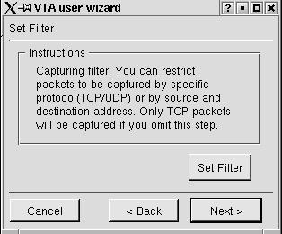
Figure 3.2.2 VTA Capturing Filter Window
The user can click on the "Set Filter" button to specify what kind of packets he wants to capture. The VTA filter selects which packets will be captured and visualized. It provides two tab widgets: protocol & device, and address. Figure 3.2.3 shows the protocol & Device tab widget.
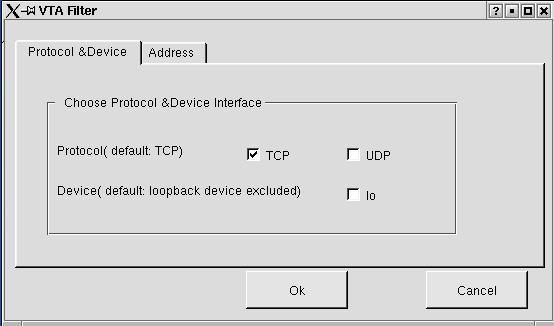
Figure 3.2.3 VTA Filter -- protocol & device
In the protocol & device tab widget, the user can specify whether
to capture TCP or UDP protocol packets or both. The default is TCP protocol.
He can also choose to exclude or include the loopback device. The loopback
device is
excluded by default.
Figure 3.2.4 shows the address tab widget. Here the user can generate an expression to feed to the pcap library filter. The expression can be a combination of "or" or "and" relationship of the source and destination IP address and port number. If no specification is given, all packets meet the protocol and device requirements will be dumped. Otherwise, only packets meet both the protocol and device requirements and for which expression is `true' will be dumped.
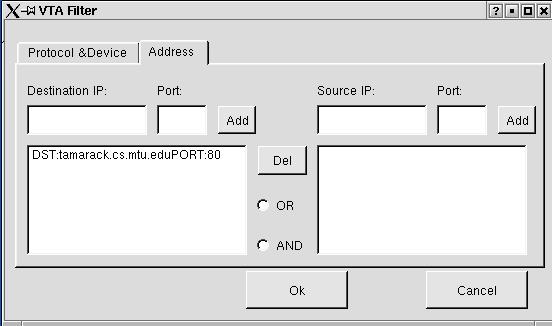
Figure 3.2.4 VTA Filter -- Address
VTA provides six kinds of views to illustrate protocol execution details. After setting the filter, the next step of the user wizard is to select what kind of views the user want to open. Figure 3.2.5 shows the select view window. The default views are currently set to the timeline and packet list view.
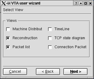
Figure 3.2.5 Select View Window
VTA provides a step mode and a non-step mode. The step mode will enable user to deliver only one packet to the views once a time, while the non-step mode will deliver packets to the display views in the same speed of capturing. In the step mode, the user has to click on the step icon or choose "step" in the control menu to allow the next packet to be delivered to the views. Figure 3.2.6 shows the step or non-step window of the VTA user wizard.
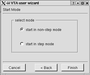
Figure 3.2.6 Step or non-step window
If the user choose Current Active Sockets mode in the data specification window, he will be presented with the active socket window, which will bring up a list of all current active sockets. The user may select any number of these sockets, and all data destined for one of these sockets will be displayed. Figure 3.2.7 shows the active socket window in the user wizard.
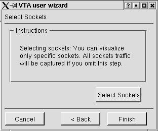
Figure 3.2.7 Active Socket Window
Clicking on the "Select Sockets" button would bring the user to the list of active sockets. The list contains all active tcp or udp sockets belonging to the user running vta. Figure 3.2.8 shows the list of active sockets.
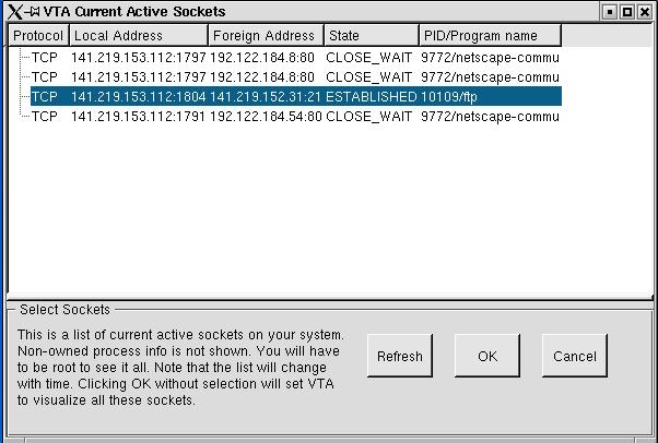
Figure 3.2.8 List of active sockets
Next Topic The VTA Views